
Understanding ISO 5211 Valve Mounting: A Guide for Engineers
- marketing96225
- Jul 24, 2025
- 3 min read
When pairing valves with actuators, one critical standard governs compatibility and installation ease: ISO 5211. Whether you're specifying a new automated valve assembly or retrofitting existing equipment, understanding ISO 5211 valve mounting is essential for proper torque transfer, alignment, and long-term reliability.
In this guide, we’ll demystify ISO 5211, explain what an ISO valve mounting flange is, and
show you how to use the F-series ISO mount standard for successful valve-actuator pairing.
What Is ISO 5211?
ISO 5211 is an international standard that defines a mounting interface between valves and
actuators. It standardizes bolt circle dimensions, shaft sizes, and flange designs—ensuring that actuators from one manufacturer can fit valves from another, without custom brackets or
machining.
This benefits engineers and OEMs by:
• Streamlining the valve automation process
• Reducing integration costs
• Supporting interchangeable parts
• Improving maintenance and upgrade flexibility
What Is an ISO Valve Mounting Flange?
An ISO valve mounting flange is the standardized top face of a valve where an actuator is
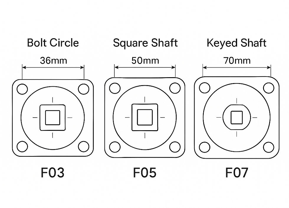
attached. These flanges follow specific dimensions outlined in the ISO 5211 table and are often referred to by F-series designations, such as F03, F05, F07, etc.
Each F-series code defines:
• The bolt hole pattern (bolt circle diameter, hole size, and spacing)
• The drive shaft configuration (square or keyed)
• Torque transmission method
For example:

These F-series ISO mounts ensure repeatability, precision, and compatibility in actuation systems.
Why ISO 5211 Valve Actuator Compatibility Matters
Valve-actuator compatibility is not just about mechanical fit—it also affects:
Actuator torque delivery
Valve sealing performance
Stem alignment and stress
System longevity
Using a mismatched or non-standard mount can lead to misalignment, excessive wear, or even catastrophic failure. That’s why selecting a ISO 5211 valve actuator ensures you're using a globally accepted standard that promotes reliability and performance.

Key Components of ISO 5211 Mounting
Bolt Circle Dimensions Ensures actuator mounts securely with four or more bolts evenly spaced on a circular flange.
Drive Shaft InterfaceTypically a square or keyed shaft, allowing direct torque transfer without a coupling.
F-Series Designation Commonly listed in both valve and actuator spec sheets. Match these to ensure correct pairing.
Adaptability ISO 5211 allows multi-pattern flanges (e.g., F05/F07 combo) for flexible installation options.
How to Select the Right ISO 5211 Mount
Here’s how engineers typically approach this:
Determine Valve Torque Requirements Know the operating torque of your valve under system conditions.
Select an Actuator with Adequate Output Torque Add a safety factor (typically 25–30%).
Match ISO Mounting Flange (F-Series) Ensure the actuator’s flange pattern and drive shaft match the valve's ISO mount.
Check Shaft Depth and Engagement Proper engagement ensures smooth torque transmission.
Confirm Compatibility with Automation Accessories Limit switches, positioners, and NAMUR solenoids should integrate with your selected actuator.

Enolgas USA and ISO 5211 Valves
At Enolgas USA, our automated valve solutions are designed with ISO 5211 valve mounting flanges for seamless actuator integration. We supply brass and stainless valves pre-configured for F03, F05, F07, and higher mounting interfaces—perfect for use in HVAC, industrial process control, and OEM automation systems.
Our customers—engineers, system designers, and OEMs—trust our ISO 5211 valve actuator assemblies for their precision, repeatability, and long-term durability.
Final Thoughts
Understanding ISO 5211 isn't just a matter of compliance—it's the foundation for effective valve-actuator compatibility in today's automated flow systems. By selecting valves and actuators that follow the ISO valve mounting flange standard, engineers gain confidence in installation, performance, and long-term maintainability.
Looking for expert help configuring ISO 5211-compliant valve assemblies?
Contact Enolgas USA today to speak with a technical specialist.


Comments